- Understanding nodes
Understanding nodes
Node elements
Overview
Nodes are the fundamental element of mind maps. Although nodes appear simple at first, they have many optional elements that can increase their functionality.
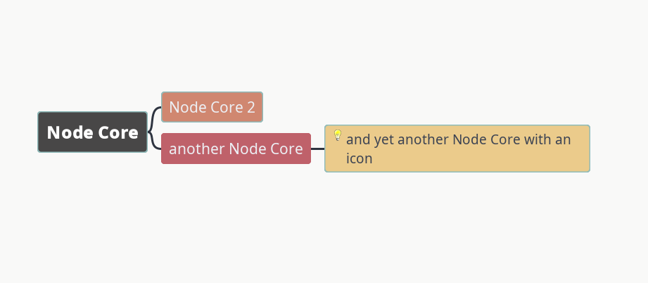
What appears to be the whole node at first is actually just the node core. If you create a new node and begin typing, the text is entered in the node core by default. Beginning users generally limit their use of nodes to the node core.
Additional information can be stored in nodes outside the core as node details, node notes, and node attributes.
Node core
The node core is the only part of the node that is always visible whenever the node itself is visible. The node core can itself contain several types of information: text (including numbers), icons, images, and links.

The text in the node core can be interpreted or parsed by Freeplane in different ways, which can be set in the Format Panel drop-down menu Core text->Format.
To understand the implications of this setting, see (to be added).
Node Details
Purpose
Node details, seen beneath the node core, displays closely-related information about the node core text.
It adds meaning to the node. One way of looking at this relationship is like a book title and its sub title.
It can elaborate, embellish, clarify, define, etc. - like a child node.
But sometimes a child node seems too distant.
Even images can be placed in node details.
Node details can represent many different relationships to the node core.
The following examples are in this format:
node core / node details
parenthetical: dialog / floating editor
appositional: Sam / my dog
factual detail: end of WW2 / Sept 2, 1945
elaboration: our wedding / beautiful day - all family members there
And so on to meet your needs.
Using node details
There are three operations or actions you can perform on node details
- Creating and editing node details
- Hiding node details
- Removing node details
Create or edit node details
When a node is selected, you can create a detail for it, if none already exists, or you can edit an already-created detail. While typing your text, to force a line break, press Shift+Enter.
There are two methods to choose from.
1. In-line editing, directly beneath the node. In-line editing offers fairly basic editing tools (via right-click or hotketys on selected text). When done typing, either
- press "Enter" to save the detail and exit the in-line editor
- press "Insert" to save the detail and create a new child node.
- Or, press "Esc" to cancel and exit the in-line editor without saving your work.
To access in-line editing: Select a node then either
- press F3
- use the Edit menu > Node properties > Edit node details in-line
- Command search (Ctrl+F1), type "details", choose the matching menu item
- right-click on the node > Edit > Edit node details in-line.
- double-click on node details (if details already exist for the node).
2. Dialog editing in a floating editor. The details dialog, a basic text editor, has more robust editing tools (via a menu bar, a toolbar, and hotkeys). Hyperlinks can be created in node details - but only in the node details dialog (Ctrl+H). When done typing, either:
- click the "OK" button to save the detail and exit the dialog (keyboard hotkey: Alt+O).
- Or, to cancel, press "Esc" to exit the dialog without saving your work.
To access dialog editing: Select a node then either
- press Ctrl+F3
- use the Edit menu > Node properties > Edit node details in dialog
- use Command search (Ctrl+F1), type "details", choose the matching menu item
- right-click on the node > Edit > Edit node details in dialog.
Hide node details
Hiding node(s) details folds the detail out of view, leaving only a sliver visible and a small down-pointing arrow (on the bottom left corner of the node core) to mark the presence of node(s) details (known as a toggle). Hovering over such a node with display the details in a tooltip popup. Clicking the toggle displays or hides the details of that node.
Hiding node details is useful to free a bit of map real estate, viewing the details when you need remember its contents. It also can help when presenting your map to others - you can reveal the node details at an appropriate time as you step through your map. Additionally, some node details may contain confidential information you do not want others to see but which you need to have access to.
Hide node details is a toggle, hiding details then showing them.
Note: even when node details are hidden, you can see it by hovering over the node.
To access: Select the node(s) then either
- press Alt+F2
- use the View menu > Hide details
- use Command search (Ctrl+F1), type "details", and choose the matching menu item
- click the toggle arrow (lower left corner of node core)
Remove node details
Remove node details will delete the node details content from one or more nodes.
To access: Select one or more nodes then either use
- the Edit menu > Node properties > Remove node details
- Command search (Ctrl+F1) > type "details" > choose the option matching the menu item
Changing node details appearance (Styles)
The appearance of node details is controlled by the Details style, one of every map's Predefined styles. You can change its appearance in the Style editing dialog:
- Ctrl+F11
- Format menu > Manage Styles > Edit styles
- Command search (Ctrl+F1) > type "edit style" > choose the option matching the menu item
You can make changes by selecting "Details" (under "Default") then make changes using the menu, toolbar, properties panel, and hotkeys.
see Styles
Miscellaneous
The Find-Replace dialog has a sortable column labeled "Details" which lets you see which nodes in the map contain text in its node details.
The Filter toolbar defaults to searching node core, details, and notes.
But you can restrict Find's scope by looking only in Details.
A node's children can be converted to attributes.
The child(ren) node core(s) contents convert to attribute name(s);
node details convert to attribute value(s).
(Similarly, attributes can be converted to child nodes.)
Node Notes
Node Attributes
Attributes can be defined for each node. They are displayed in a 2-column table
| Key | Value |
|---|---|
| Name | Mac |
| Username | macmarrum |
The actions related to Attributes can be listed in Help->Command Search (Ctrl+F1) – search for attribute
Once you have at least one attribute, you can right-click on the table to perform actions (New, Delete, Move up, Move down).
Alternatively, you can manage attributes in View->Controls->Tool panel – tab Attributes
Edges
Connectors
Unlike edges, connectors must be added manually.
To add a connector between two nodes, select them, right-click for a context menu and choose Connect (Ctrl+L) or use the hot key.
Another way is to Ctrl+Shift + drag one node onto another.
On some systems it's also possible to right-click + drag one node onto another.
It's possible to add several connectors at one go by selecting more than two nodes. In this case the last selected node is the target.
Connectors' properties can be edited.
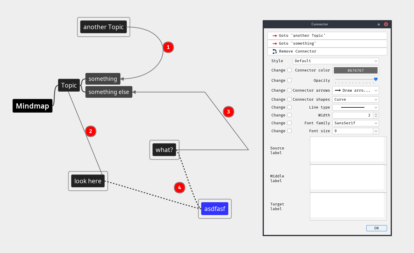
When you right-click a connector (it's best to select one of the connected nodes first), the Connector dialog appears.
Here you can set formatting properties individually or select a Style (or both), set labels' text and remove the connector.
See also Connector styles below.
By default, a connector's shape is Curve①.
The other options are Line②, Linear path③ and Simulate edge④.
The last one does exactly that: simulates an edge between the nodes.
Freeplane achieves this by applying the formatting properties of the edge defined for the target node, ignoring the Connector-dialog properties.

The shape of Curve①. Line② and Linear path③ can be changed using curve-shaping of either end – just click on the line near a node (it's best to select the node first).
You will see handles appear.
By dragging your mouse up to ~50% of the distance between the nodes, the near handle is adjusted.
Going beyond ~50% or clicking near the middle adjusts both handles at once.
You'll often need to repeat your click-drag-release several times before you get the expected result, i.e. without affecting the far end.

Hidden connectors
Connector lines can be hidden: Preferences…->Defaults->Connectors->Show connector lines
Alternatively, they can be displayed as the lowest level: Preferences…->Defaults->Connectors->Paint connectors behind nodes
Go to a connected node
Like for clones, the right-click node menu item Goto list the other ends of Connectors.
Same-node connectors
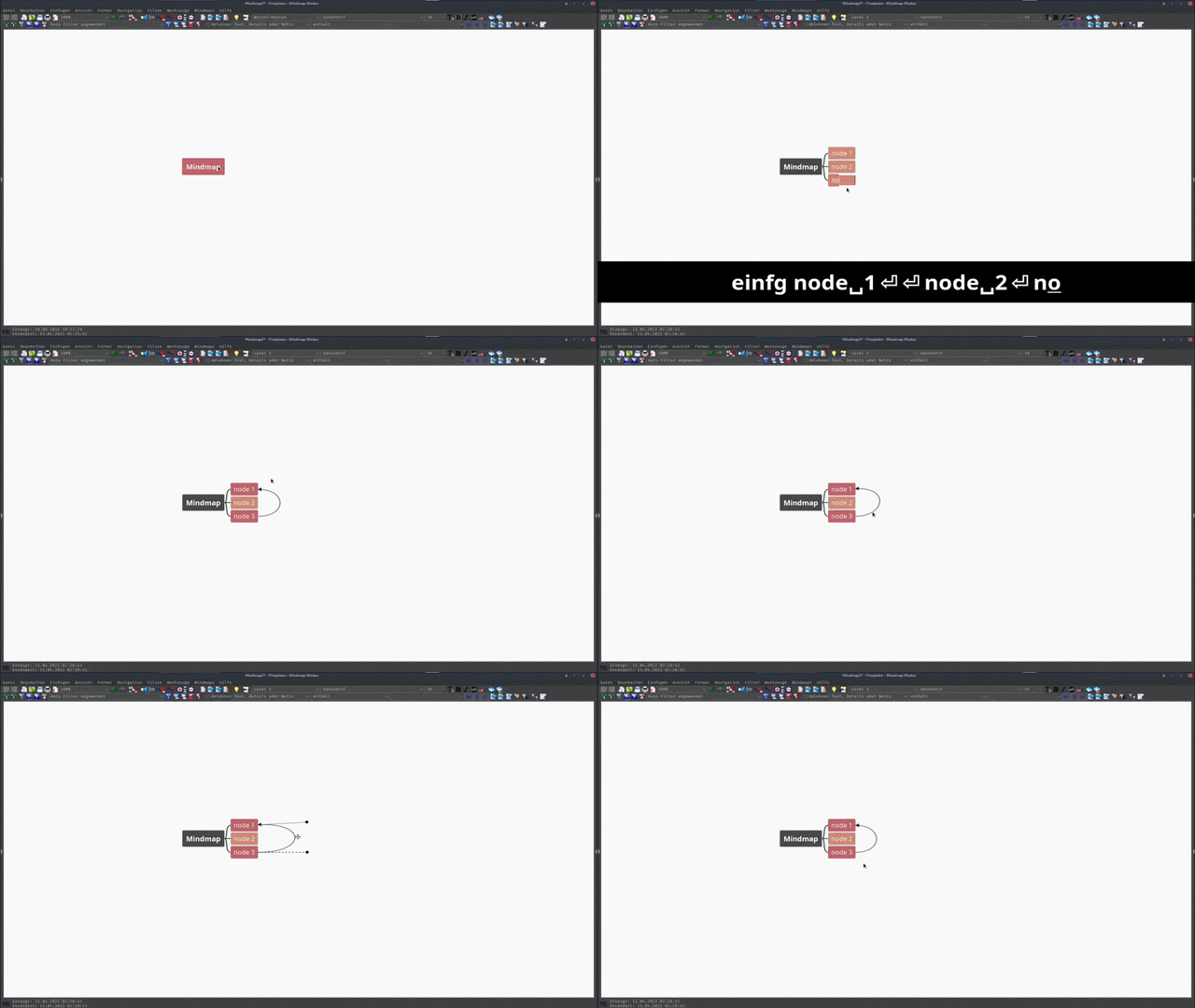
Both ends of a connector can be attached to the same node, looping back to itself.
To create such a connector, right-click a single node and select Connect (Ctrl+L) or use any of the other methods described above.
When using Line as the type, the connector appears one-ended.
Line is often used to draw an arrow going out of a node into empty space (as seen in Freeplane Help->Tutorial).
Connector styles
Connectors use styles. The concept is the same as for nodes (see Styles), i.e. a bundle of connector formatting properties is saved as a connector style. Technically, a connector style is part of a node style. When a node style has a connector defined, like Default has, the style becomes also a connector style.
When a connector is added, a style is applied to it, which determines how the connector looks like.
By default, it's the Default style.
There's an option to apply a style based on the style defined on the source or the target node.
The option can be enabled in Preferences (Ctrl+COMMA) -> Defaults -> Connectors -> Assigns node dependant styles to new connectors.
The logic is the following:
if the source node has a style applied which has a connector defined, the style is applied to the connector;
otherwise, the target node is checked for the same.
The style of a connector can be switched in the Connector dialog.
To open it, right-click on a connector.
It's best to select a connected node first, to indicate which connector the dialog should open for.
Types of nodes
In addition to standard nodes, there are some special types of nodes:
- the root node
- free nodes

The root node
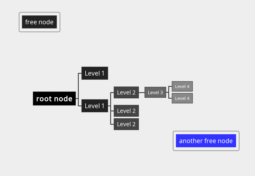
Every mind map begins with a central node called the root node. Node levels are defined based on their distance from the root node.
Free nodes
Free nodes are nodes that appear separate from the map hierarchy.
They are "free" because they can be freely positioned around the map.
They are not automatically positioned like other nodes and they generally do not affect other nodes when they are changed or moved.
Any node can be freed by enabling Edit->Free positioned node (set/reset).
A special type of free node is a Floating node.
It can be added by Ctrl+double-click on the map background, or by Insert->New node->New floating node.
Note: although Floating nodes are positioned independently, technically, they are first-level nodes that are invisibly connected to the root node.
You can add children, parents, or siblings to free floating nodes, but you may get unexpected behaviors.
Technically, a Floating node is simply a node with three features:
- they are given the style
Floating node, which connects to other nodes with invisible edges - they have the toggle at menu item
Edit->Position node independentlyset to "on" - their oval positioning handle is filled and blue rather than unfilled and red
Other nodes can also be given the style Floating node and can be set to be positioned independently: Edit->Free positioned node (set/reset).
Clone nodes
Node groups
Summary nodes

Summary nodes have brackets that suggest that their content summarizes a group of sibling nodes. Technically, summary nodes are specially marked sibling nodes of the summarized nodes. Summary nodes can include other summary nodes within their brackets, creating the impression of a "reverse" map with branches joining rather than splitting.
Summary node brackets can be customized the usual way, by changing the edge formatting properties: width, line type, color. The only exception is its shape (aka edge style) that isn't customizable.